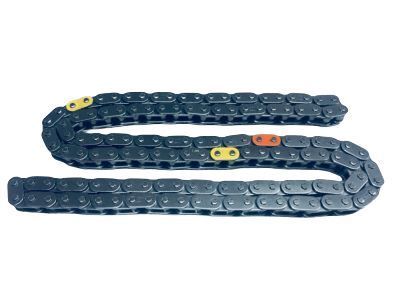
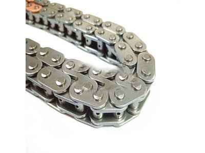
To remove the components, first disconnect the cable from the negative battery terminal, then remove the drive belt and the alternator. Next, take off the valve cover and the ABS actuator if equipped, ensuring to remove the three gaskets from the camshaft bearing caps on 2008 and later models. With the parking brake applied and the rear wheels blocked, loosen the right front wheel lug nuts, raise the front of the vehicle, and support it securely on jack stands before removing the right front wheel and splash shield. Drain the cooling system while removing the power steering pump without disconnecting the fluid lines, tying it to the body to keep it out of the way. Position the number one piston at TDC on the compression stroke, confirming alignment of the timing mark on the crankshaft pulley with the "0" mark on the timing chain cover and the camshaft sprocket marks with the marks on the camshaft front bearing caps. Remove the crankshaft pulley/vibration damper without rotating the engine from TDC, supporting the engine from above or below. Remove the passenger side engine mount and movement control rod, followed by the drive belt tensioner(s) and the crankshaft position sensor from the timing chain cover, along with the bolt securing the wiring harness. Detach the main wiring harness junction and remove the timing chain tensioner from the rear side of the timing chain cover, then pry off the cover after removing the fasteners. Slide the crankshaft position sensor reluctor ring off the crankshaft, remove the timing chain tensioner pivot arm/chain guide, and lift the timing chain off the camshaft sprockets, removing the timing chain and crankshaft sprocket as an assembly. For 2008 and later models, remove the movement control rod mounting bracket from the front of the timing chain cover, then remove the cover fasteners and pry off the cover. Remove the O-rings from the crankcase, the top chain guide mounting bolt and guide, and extend the tensioner plunger until a pin can be inserted into the alignment holes. Remove the mounting bolts and the timing chain tensioner, followed by the timing chain tensioner pivot arm/chain guide and the stationary timing chain guide. Lift the timing chain off the camshaft sprockets and remove the timing chain and crankshaft sprocket as an assembly. To remove the camshaft sprockets, loosen the bolts while holding the hex on the camshaft with a wrench, noting the identification marks before removal. Visually inspect all parts for wear and damage, checking the timing chain for loose pins, cracks, worn rollers, and side plates, as well as the sprockets for hook-shaped, chipped, and broken teeth. Measure the timing chain for stretching and the diameter of the timing sprockets for wear, replacing them as necessary. Check the chain guides for excessive wear and inspect the chain guide oil hole for clogging. For installation, remove all traces of old sealant from the timing chain cover and the mating surfaces, position the camshafts with the dowel pins at the top, and install both camshaft sprockets in their original locations. Ensure the TDC marks on the camshaft sprockets are aligned, install the stationary timing chain guide, loop the timing chain around the crankshaft sprocket, and align the No.1 colored link with the mark on the crankshaft sprocket. Slip the timing chain into the lip of the stationary timing chain guide and over the exhaust camshaft sprocket, then around the intake camshaft sprocket, aligning the remaining colored links with the marks on the camshaft sprockets. Remove slack from the chain and install the timing chain tensioner pivot arm/chain guide, ensuring the tab on the pivot arm can't move past the stopper on the cylinder head. Reconfirm that the number one piston is at TDC and that the timing marks are aligned. Install the crankshaft position sensor reluctor ring with the "F" mark facing outward, apply RTV sealant to the timing chain cover sealing surfaces, and install the cover with bolts in their original locations, tightening them evenly. Reload and lock the timing chain tensioner, lubricate the O-ring, and install the tensioner into the timing chain cover. Install the crankshaft pulley/vibration damper, rotate the engine counterclockwise slightly to set the chain tension, and for 2008 and later models, temporarily install the crankshaft pulley bolt and rotate the crankshaft counterclockwise until the keyway is pointing to the 10 o'clock position. Align the TDC marks on the camshaft sprockets, install the stationary timing chain guide, loop the timing chain around the exhaust camshaft sprocket, and align the yellow-colored link with the timing mark. Guide the chain into the stationary chain guide, align the crankshaft sprocket with the pink-colored link, and slip the timing chain around the intake camshaft sprocket. Rotate the crankshaft clockwise until the keyway is pointing to the 12 o'clock position, install the tensioner guide and mounting bolt, then install a new gasket and the tensioner. Confirm that the number one piston is still at TDC and that the timing marks are aligned, install the top chain guide mounting bolt and guide, apply RTV sealant to the timing chain cover sealing surfaces, and install the cover with bolts in their original locations. Tighten the bolts in sequence, install the movement control rod mounting bracket, and tighten the bolts. Finally, rotate the engine clockwise at least two revolutions and reposition the number one piston at TDC, visually confirming the alignment of the timing marks. The remainder of the installation follows the reverse of removal.
Posted by ToyotaPartsDeal Specialist 

